Showing posts with label CLAAS repair. Show all posts

Monday, June 23, 2025

How to Install Threshing Drum for CLAAS Lexion 480

This instruction show you guide on how to install the  threshing drum  for CLAAS Lexion 480.

Installing the threshing drum 

1. Using a suitable lifting device, guide the drum into the machine housing from the right-hand side. While doing so, place a suitable tube onto the shaft end on the left-hand side. Use this tube to guide the shaft end into the notch.


 Related Contents:

CLAAS Diagnostic Kit USB Interface

[05.2021] CLAAS CDS 7.5 Diagnostic System Development Level 

Class Parts Doc EPC Agricultural 2025 2011 Free Download


2. Support the underside of the drum with wooden wedges on both sides. 

3. The bearing bore, taper lock sleeve and the shaft seat must be dry and free from grease.

4. On the right-hand machine side, assemble the bearing assembly (8 – 12), the spacer (7) and the assembly cover (6) on the shaft end. 


Tuesday, August 27, 2024

How to Remove Straw Spreader Bearing Housing for CLAAS Lexion 480

How to Remove Straw Spreader Bearing Housing for CLAAS Lexion 480


Related Contents:

CLAAS Diagnostic Kit USB Interface

[05.2021] CLAAS CDS 7.5 Diagnostic System Development Level 

Class Parts Doc EPC Agricultural 2024 2011 Free Download


Procedures:
Removing the straw spreader drive belt (36).
Unscrew the angular brace (45)
Unscrew hex. socket head bolts of set collar (20).
Screw the end of the hex. socket head bolts into the open hole of the toothed belt pulley (threaded face at the set collar).
This pulls the set collar off of the toothed belt pulley.

Loosen the linch pin (28) and remove the complete straw spreader to the bottom.

Unscrew the mushroom head bolts (22) from the bearing housing (23) and remove the complete bearing housing (23) to the bottom.


Disassembling the straw spreader bearing housing
Determine dimension (X) from shaft end to the bracket (H).
Mark the position of bracket (37) and shaft (36) with respect to each other.

Loosen hex. socket head bolt (38) and remove bracket (H).

Unscrew hex. bolts (27) of conical guard (25) and remove the washer (26).
Secure sprocket (19) on the shaft (24) with the expansion pins (36).

Drive expansion pins (30 and 31) out of the bearing bushing (32).

Drive shaft (36) out of the bearing housing (23), using a brass punch.
Remove circlip (35). Drive out bearing (33) and spacer tube (13) with a brass punch.

Wednesday, March 13, 2024

ClAAS Lexion 480 Checking / Topping up the Refrigerant Oil Level

ClAAS Lexion 480 Checking / topping up the refrigerant oil level at the air conditioner compressor.


Related Contents:

CLAAS Diagnostic Kit USB Interface

[05.2021] CLAAS CDS 7.5 Diagnostic System Development Level 

Class Parts Doc EPC Agricultural 2024 2011 Free Download


NOTE: The oil level at the compressor must be checked when a new air conditioner compressor or a newly sealed air conditioner compressor has been built in.

Tuesday, March 9, 2021

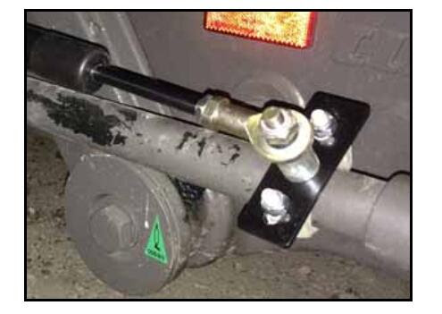
How to Install WAS for CLAAS Lexion 700 Single Steering Cylinder Models

Here is a step-by-step guide on how to install WAS CLAAS Lexion 700 Single Steering Cylinder Models.More repair manual please refer to:CLAAS Webtic Offline Repair and Service

1. Locate the WAS mounting location on the machine’s steering cylinder.


1
2. Remove the nuts and clamp from the 4-1/2” muffler clamp (P/N 435-3003-070) and install the U-bolt around the right end of the steering cylinder barrel with the U-bolt ends pointing up and angled toward the rear of the machine.
3. Install the clamp on the ends of the U-bolt and secure it using the clamp’s two nuts


4. Insert the M10 x 1.5 pitch x 60 mm bolt (P/N 311-0070-025) through the center hole in the large WAS rod
mounting bracket (P/N 107-0172-431).
5. Install a 0.406” ID x 0.75” OD x 1” spacer (P/N 107-0172-038) on the end of the installed M10 bolt.
6. Install the WAS mounting bracket on the legs of the installed muffler clamp using 3/8” flat washers (P/N
313-2300-014) and 3/8”-16 lock nuts (P/N 312-4001-109).
Note: The bracket should be positioned so that the M10 bolt points away from the clamp.

CLAAS Part Doc EPC 2016 Download


7. Install the base-end (end with the cable connection) of the WAS on the M10 bolt and spacer, securing it with one M10 lock nut (P/N 312-4000-208)


8. Position the WAS parallel to the tie rod and extend the rod of the WAS to until it is 1” from full compression
or 1” from full extension, depending on whether the rear wheels are turned fully to the left or to the right.
9. Install a muffler clamp (P/N 435-3003-030 or 435-3003-059 as appropriate based on the size of the tie rod) on the tie rod in the location of the M10 ball mount on the rod-end of the WAS.
Note: Position the muffler clamp with the U-bolt ends pointing up and angled toward the rear of the machine.
10. Insert the M10 x 1.5 pitch x 60 mm bolt (P/N 311-0070-025) through the center hole in the small WAS rod mounting bracket (P/N 107-0172-030).
11. Install a 0.406” ID x 0.75” OD x 1” spacer (P/N 107-0172-038) on the end of the installed M10 bolt.
12. Install the WAS mounting bracket on the legs of the installed muffler clamp using 5/16” flat washers (P/N 313-2300-012) and 5/16”-18 lock nuts (P/N 312-4000-059).
Note: The bracket should be positioned so that the M10 bolt points away from the clamp.
13. Install the rod-end of the of the WAS on the M10 bolt and spacer, securing it with one M10 lock nut (P/N 312-4000-208).
14. Tighten all nuts used to install the WAS.
15. Route the cable from the base-end of the WAS toward the left side of the machine’s frame, routing it so that the cable is not near moving parts or heat sources. Secure with plastic cable ties as necessary.

Class Parts Doc EPC Agricultural 2016 2011 Free Download 

How to Solve AGCO Sisu T3 ECU Temperature No Signal?

This instruction show you guide on how to Solve AGCO Sisu T3 ECU Temperature No Signal SPN 1136 - FMI 02?   What is you need? AGCO 2x4 canus...